


60A Miniature High Power Relay With Big Gap
● 60A switching capability● Contact gap ≥ 1.8mm
● Strong anti-shock, anti-vibration and high reliability
● Product in accordance to IEC60335-1 available
● RoHS Compliant
Model:NT90W
Send Inquiry PDF DownLoad
Product Description
Features
50A/60A switching capability.
Contact gap: 1.8mm.
Ideal for charger.
Applicable to inverter used for photovoltaic power generation systems.
Product in accordance to IEC 60335-1 available
Ordering Information

1 Part number: NT90W
2 Load: 50:50A 60:60A
3 Contact arrangement: A:1A C:1C
4 Enclosure: S: Wash tight E: Flux proof
5 Coil rated voltage(V): DC:5,6,9,12,15,18,24,48 6 Contact material S: AgSnO2
7 Contact gap: S:1.8mm; Nil: Standard gap
8 Coil power: Nill:2.25W; L:1.2W
9 W:335 compliant Nil:Standard
Contact Data
| Contact Power | 1.2W | 2.25W | |
| Contact Arrangement | 1A SPSTNO) 1C(SPDT(B-M)) | 1A(SPSTNO) | |
| Contact Material | AgSnO2 | AgSnO2 | |
| Contact Rating(Resistive) |
NO:50A,60A/277VAC |
50A/277VAC 35A/277VAC(S Gap) 40A/30VDC |
|
| Max. Switching Power | 14400VA | 1200W 13850VA | |
| Max. Switching Voltage | 280VAC | 1200W 13850VA | |
| Max. Switching Current | 60A | ||
| Contact Resistance | ≤30mΩ | Item 4.12 of IEC61810-7 | |
| Operational Life | Electrical |
1×10⁴ (NO:60A/277VAC,Resistive load, 65℃, 1s on 9s off) 2×10⁴ (NO:50A/277VAC,Resistive load, 65℃, 1s on 9s off) 1×10⁴ (NC:35A/277VAC,Resistive load, 65℃, 1s on 9s off) 3×10⁴ (S Gap)(35A/277VAC,Resistive load, 85℃, 1s on 9s off) |
Item 4.30 of IEC 61810 -7 |
| Mechanical | 1×10⁶ | Item 4.31 of IEC 61810-7 | |
Coil Parameter
| Dash numbers | Rated voltage VDC |
Coil resistance Ω±10% |
Pick-up voltage V(max) (75% of rated voltage) | Drop-out voltage V(min) (10%of rated voltage) | Coil power W | Operate time ms | Release time ms | |
| Rated | Max | |||||||
| 005-1200 | 5 | 6.5 | 20.8 | 3.75 | 0.5 | 1.2 | ≤15 | ≤10 |
| 006-1200 | 6 | 7.8 | 30 | 4.50 | 0.6 | |||
| 009-1200 | 9 | 11.7 | 67.5 | 6.75 | 0.9 | |||
| 012-1200 | 12 | 15.6 | 120 | 9.00 | 1.2 | |||
| 015-1200 | 15 | 19.5 | 187.5 | 10.25 | 1.5 | |||
| 018-1200 | 18 | 23.4 | 270 | 13.50 | 1.8 | |||
| 024-1200 | 24 | 31.2 | 480 | 18.00 | 2.4 | |||
| 048-1200 | 48 | 62.4 | 1920 | 36.00 | 4.8 | |||
| 012-2250 | 12 | 15.6 | 64 | 9.00 | 1.2 | 2.25 | ≤15 | ≤10 |
| 024-2250 | 24 | 31.2 | 256 | 18.00 | 2.4 | |||
After the energization time of 100 ms with rated voltage, the coil voltage can be reduced to 40%~50% of the rated voltage.
Characteristics
| Insulation Resistance | 1000MΩ min (at 500VDC) | Item 4.11 of IEC 61810-7 |
| Dielectric Strength |
|
|
| Between Contacts |
50Hz 1500V 2500V(S Gap) |
Item 4.9 of IEC 61810-7 |
| Between Contact and Coil |
50Hz 2500V 4000V* |
Item 4.9 of IEC 61810-7 |
| Shock Resistance | Functional: 98m/s² | Item 4.26 of IEC 61810-7 |
| Destructive: 980m/s² | ||
| Vibration Resistance |
10Hz~55Hz Double amplitude 1.5mm |
Item 4.28 of IEC 61810-7 |
| Terminals Strength | 10N | Item 4.24 of IEC 61810-7 |
|
Surge Voltage (Between Coil & Contacts) |
6kV(1.2/50 μs) | Item 4.10 of IEC 61810-7 |
| Ambient Temperature | -55℃~85℃ | |
| Relative Humidity | 5% to 85% | Item 4.16 of IEC 61810-7 |
| Mass | 27g | Item 4.7 of IEC 61810-7 |
* Please contact the sales representative if 4000V is required.
Safety Approvals
| Safety approval | UL&CUR | TüV | CQC |
| Load |
50A/277VAC 40℃ 35A/277VAC 85℃ |
35A,40A,50A/277VAC 35A,40A,50A/250VAC |
50A/277VAC 40A/277VAC,250VAC 35A/277VAC,250VAC |
Dimensions(mm)
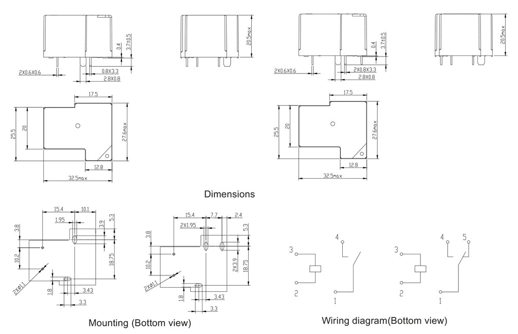
CAUTION
In case of no tolerance shown in outline dimension: outline dimension ≤1mm tolerance should be ±0.2mm outline dimension >1mm and ≤5mm, tolerance should be ±0.3mm; outline dimension >5mm, tolerance should be ±0.4mm.